 英语
英语 西班牙语
西班牙语 阿拉伯语
阿拉伯语Cat:Products
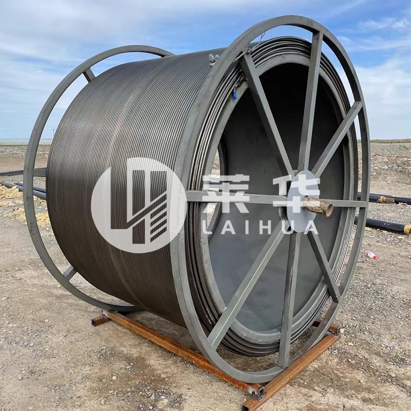
Continuous tubing, also known as flexible tubing or flexible tubing, is widely used in the fields of well workover, logging and drilling, etc. Its pro...
See Details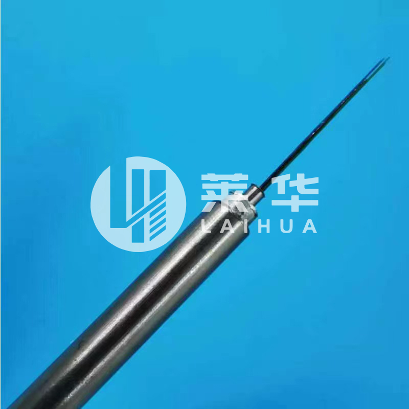
Content
Stainless steel fiber optic testing cable is specialized test assemblies designed with protective stainless steel armoring to withstand harsh environmental conditions during field testing and laboratory measurements. These cables typically feature stainless steel braiding or interlocking armor over standard fiber optic test cables, providing mechanical protection, crush resistance, and flexibility that standard test cables cannot offer in demanding industrial or outdoor testing scenarios.
These ruggedized test cables serve critical functions in telecommunications, data centers, military installations, and industrial fiber optic networks where standard plastic-jacketed test cables would fail due to physical stress, rodent damage, or environmental exposure. Understanding their construction, specifications, and proper application is essential for network technicians and engineers conducting reliable fiber optic testing.
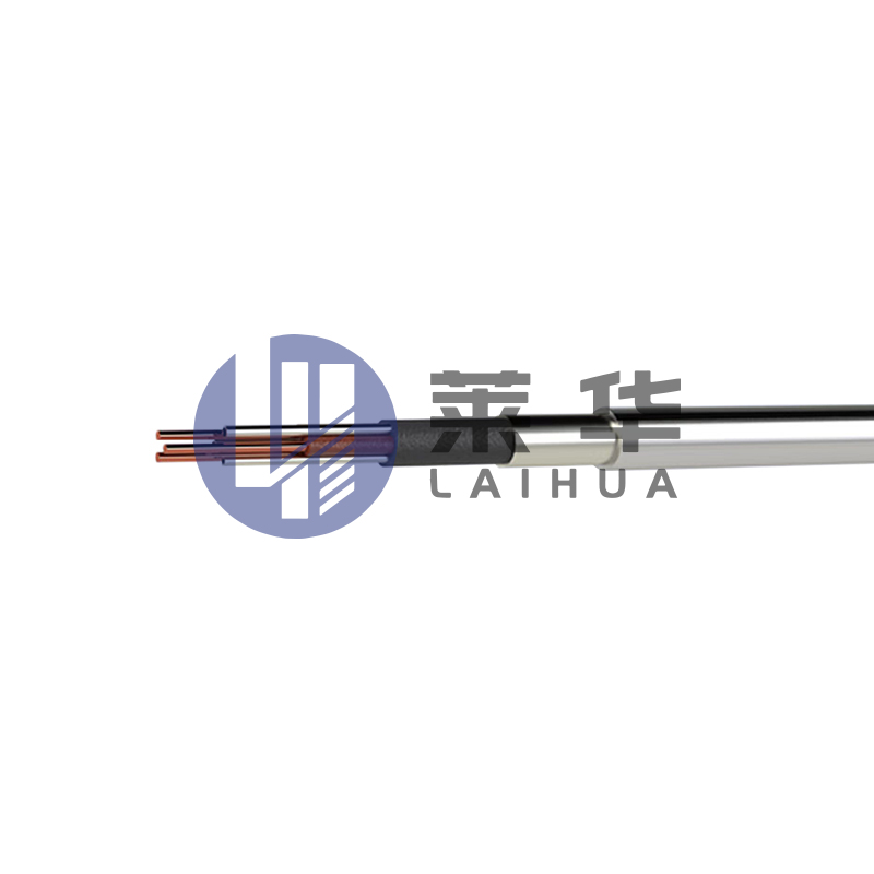
The construction of stainless steel fiber optic testing cables involves multiple layers designed to balance protection with signal integrity. The core structure begins with standard single-mode or multimode optical fibers, typically 900μm tight-buffered or 3mm jacketed, surrounded by aramid strength members.
Two primary stainless steel armor configurations dominate the market:
The outer jacket over the stainless steel layer typically uses polyurethane (PU) or low-smoke zero-halogen (LSZH) materials. PU jackets provide excellent abrasion resistance and flexibility down to -40°C, while LSZH jackets meet fire safety requirements for indoor testing applications in data centers and telecommunications facilities.
Understanding the technical specifications ensures proper cable selection for specific testing requirements. The following parameters directly impact measurement accuracy and cable longevity.
| Parameter | Single-Mode Specification | Multimode Specification |
|---|---|---|
| Insertion Loss | ≤0.3 dB (@ 1550nm) | ≤0.4 dB (@ 850nm) |
| Return Loss | ≥50 dB (UPC), ≥60 dB (APC) | ≥35 dB |
| Operating Temperature | -40°C to +85°C | -40°C to +85°C |
| Tensile Strength | 200-500 N | 200-500 N |
| Minimum Bend Radius | 10-15x OD (dynamic) | 10-15x OD (dynamic) |
The insertion loss specification is critical for accurate power meter and OTDR measurements. High-quality stainless steel test cables maintain insertion loss below 0.3 dB across standard telecommunications wavelengths, ensuring measurement errors remain within acceptable tolerances defined by IEC 61280 standards.
Stainless steel fiber optic testing cables excel in environments where standard test cables face rapid degradation or failure. Their deployment spans multiple industries with distinct requirements.
During outside plant (OSP) fiber installation and maintenance, technicians frequently drag test cables across pavement, through conduits, and over rough terrain. Standard cables typically fail within 3-6 months of field use, while stainless steel armored variants maintain integrity for 2-3 years under identical conditions. This durability proves essential for telecommunications contractors conducting daily OTDR testing and loss measurements on aerial and buried fiber routes.
Factory automation networks, oil and gas facilities, and power generation plants require fiber testing in areas with heavy machinery, chemical exposure, and extreme temperatures. Stainless steel cables withstand:
Defense applications demand test cables meeting MIL-STD-810 environmental specifications. Stainless steel construction provides required protection during tactical fiber network deployment and aircraft avionics testing, where cables face repeated setup/teardown cycles and exposure to jet fuel, hydraulic fluids, and wide temperature extremes from -55°C to +125°C.
While data centers are controlled environments, testing during construction phases exposes cables to concrete dust, foot traffic, and temporary routing over sharp edges. Armored test cables prevent costly fiber connector damage during commissioning of high-density MPO trunk systems where replacement costs can exceed $500 per connector pair for 24-fiber or 72-fiber assemblies.
Stainless steel testing cables are available with all standard fiber optic connector types, with specific configurations optimized for different test equipment interfaces.
LC, SC, ST, and FC connectors dominate single-mode and multimode test cable terminations. For OTDR testing, SC/APC connectors reduce measurement dead zones to 1-2 meters compared to 4-6 meters with UPC polish, critical when testing short patch cords or identifying connector issues in high-density installations. LC connectors serve as the standard for modern test equipment interfaces due to their compact size and consistent performance.
MPO/MTP connectors enable testing of 12-fiber, 24-fiber, or 72-fiber parallel optics systems with single insertions. Stainless steel MPO test cables incorporate precision alignment sleeves maintaining fiber-to-fiber insertion loss below 0.35 dB and crosstalk below -40 dB across all positions. These specifications ensure accurate characterization of 40G/100G/400G data center links using MPO trunk infrastructure.
Test cable sets frequently require different connectors on each end to interface between test equipment and installed fiber. Common hybrid configurations include LC-SC, LC-ST, and SC-FC combinations. Rotating adapter boots on stainless steel cables prevent jacket twisting during connector mating, extending cable life beyond 5,000 insertion cycles compared to 1,000-2,000 cycles for fixed boot designs.
Choosing the appropriate stainless steel fiber optic testing cable requires evaluating multiple factors beyond basic connector type and fiber mode specifications.
Standard lengths range from 1 meter to 30 meters, with 3-meter and 5-meter variants most common for laboratory and equipment rack testing. Field technicians typically require 10-meter or 15-meter cables for outdoor testing from equipment shelters to aerial or underground access points. Remember that cables longer than 20 meters may introduce additional insertion loss of 0.05-0.1 dB, which must be factored into link loss budgets.
Test cable fiber must match the installed network fiber to ensure accurate measurements:
Professional-grade stainless steel test cables should include individual test reports documenting insertion loss, return loss, and fiber geometry measurements. Cables meeting Telcordia GR-326-CORE requirements provide traceable certification ensuring measurement accuracy within ±0.1 dB. This certification becomes critical when test results are used for warranty claims or compliance verification.
Stainless steel armored test cables typically cost 2-4 times more than standard plastic-jacketed equivalents. However, field data shows armored cables lasting 3-5 years versus 6-12 months for standard cables in demanding applications. For a contractor performing 200 test sessions annually, investing in $150-300 armored cables versus $50-80 standard cables yields positive ROI within 12-18 months through reduced replacement frequency and avoided downtime from cable failures during critical measurements.
Despite their rugged construction, stainless steel fiber optic testing cables require proper handling and maintenance to deliver rated performance throughout their service life.
Contamination on connector endfaces remains the primary cause of measurement errors even with armored cables. Studies show that 85% of fiber optic link failures trace to dirty connectors. Implement these cleaning procedures:
Store cables in dedicated cases or cable wraps with minimum bend radius markings. Never coil cables tighter than the specified minimum bend radius (typically 10-15 times the cable outer diameter). For 6mm diameter cables, this translates to minimum coil diameters of 6-9 cm. Violating bend radius specifications can induce microbending losses of 0.5 dB or more at 1550nm wavelengths, rendering the cable unsuitable for precision measurements.
Establish baseline insertion loss measurements for all test cables when new, then retest quarterly or after 500 insertion cycles. Progressive insertion loss increases indicate developing problems with connectors or internal fiber damage. Replace cables showing loss increases exceeding 0.2 dB from baseline values or return loss degradation below 45 dB for single-mode cables.
Understanding typical failure modes enables quick diagnosis and resolution of testing anomalies attributed to cable problems rather than the network under test.
When test cables produce fluctuating insertion loss measurements varying by more than 0.1 dB between repeated connections, three root causes dominate:
Microscope inspection reveals 90% of these issues, with connector replacement resolving problems mechanical cleaning cannot address.
Cuts or abrasion through the outer jacket exposing stainless steel armor do not immediately compromise optical performance. However, exposed armor creates snag hazards and allows moisture ingress that eventually corrodes the steel and degrades the underlying fiber. Apply heat-shrink tubing over damaged sections as temporary repair, but plan cable replacement when jacket damage exceeds 25% of circumference or extends longer than 5cm.
The strain relief boot protecting the fiber-to-connector transition represents the weakest mechanical point in armored cables. Boot tearing or separation from the connector body typically occurs after 2,000-3,000 insertion cycles with improper pull angles. Replace boots using heat-shrink or crimp-style aftermarket boots rather than discarding entire cables. Quality replacement boots cost $5-15 versus $150-300 for complete cable assemblies.
The fiber optic testing cable market continues evolving to address new network architectures and testing methodologies.
Expanded beam connectors use lenses to enlarge the optical beam diameter at the mating interface, dramatically reducing sensitivity to contamination and misalignment. Stainless steel test cables incorporating expanded beam connectors demonstrate insertion loss variation under 0.05 dB across 10,000 insertion cycles without cleaning, compared to 0.2-0.3 dB variation for standard physical contact connectors. This technology particularly benefits military and industrial applications where field cleaning is impractical.
Research prototypes embed RFID tags and fiber Bragg grating sensors within armored test cables to track usage cycles, detect excessive bending, and monitor insertion loss in real-time. These smart cables will automatically alert technicians when performance degradation requires replacement, eliminating manual verification testing protocols and reducing measurement errors from deteriorated cables.
As data centers transition to 800G and 1.6T interfaces using 32-fiber, 64-fiber, and 96-fiber MPO connectors, test cable manufacturers are developing stainless steel variants supporting these ultra-high-density configurations. The primary challenge involves maintaining bend radius specifications while accommodating the larger connector housings required for 64+ fiber arrays.

Continuous tubing, also known as flexible tubing or flexible tubing, is widely used in the fields of well workover, logging and drilling, etc. Its pro...
See Details high-temperature testing cable")
Purpose: The high-temperature testing cable, combined with the high-temperature testing vehicle, is mainly used in multi-parameter testing of heavy oi...
See Details
The Stainless Steel Fibre Optic Test Cable is a special test cable that combines the durability of stainless steel with the high transmission efficien...
See Details
Instructions for the use of hydraulic control pipelines Hydraulic control pipeline, also known as capillary. Mainly used for underground capillary pre...
See Details")
Stainless steel clad pipe is a piping system that combines the durability of stainless steel with the protection of plastic. This piping system is usu...
See Details
Application field:The electric induction heating system is a complete set of electric heating devices developed by our company specifically for heavy ...
See Details
The ferrule type pipe joint consists of three parts: the joint body, ferrule, and nut. When the clamp and nut are inserted into the joint body on the ...
See Details
Continuous Tubing Skid Winch is a specially designed equipment for oilfield operations, which combines the design features of the Continuous Tubing Wo...
See DetailsE-mail: [email protected]
Phone: +86-15996597000
+86-18252893456
Whatsapp: +86-18252874678
Address: No. 3 Xinyuan Road, Nanmo Town Industrial Park, Hai'an City, Nantong City, Jiangsu Province, China
QR code on
mobile phone


Contact Us