
 英语
英语 西班牙语
西班牙语 阿拉伯语
阿拉伯语Cat:Products
Continuous tubing, also known as flexible tubing or flexible tubing, is widely used in the fields of well workover, logging and drilling, etc. Its pro...
See Details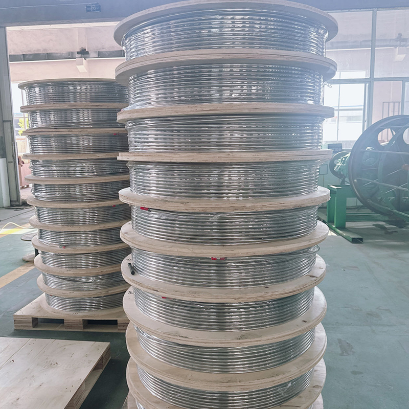
Content
A delayed pressure relief response in a refinery’s safety valve control pipeline can turn a manageable overpressure event into a catastrophic failure. When a pressure vessel or piping network exceeds its design limit, the control pipeline that signals and actuates the safety valve must react without hesitation. Any blockage, leakage, or structural compromise in that line puts equipment and personnel at risk. This guide explains what safety valve control pipelines are, how they are engineered, and which materials and practices keep them reliable under extreme conditions.
Safety valve control pipelines are the small-bore tubing and associated fittings that connect a pressure relief valve to the system it protects. They serve three primary functions: sensing process pressure, transmitting that signal to the valve’s actuating mechanism, and, in pilot-operated designs, directing the discharge flow to keep the main valve closed or open it at the set pressure. These lines are not secondary accessories; they are integral to the safety instrumented function.
Three line types dominate field practice:
If any of these paths is undersized, clogged, corroded, or mechanically damaged, the entire overpressure protection chain fails.
Engineers size control pipelines not only for flow but for pressure drop and response time. A pressure drop exceeding 3% of the set pressure in a sensing line can delay valve opening beyond acceptable limits. For a valve set at 150 psig, that means no more than 4.5 psi total loss from tap to sensing diaphragm.
A minimum internal diameter of 12 mm (½ inch) is common for sensing lines up to 15 meters long, but actual sizing must follow API 520 Part II and ISO 4126-5 guidelines. The line must be self-draining toward the valve to prevent liquid accumulation, and it must avoid pockets that could trap condensate or solid particles. A slope of at least 1:50 away from the valve inlet is a widely accepted rule.
For pilot-operated safety valves, the total pressure drop in the sensing line, including fittings, should remain below 3% of set pressure at the design flow rate. When the set pressure is below 50 psig, the drop limit tightens to 2% to maintain accuracy. Use the actual clean frictional loss, not just the nominal pipe size, to confirm compliance during design.
Safety valve control pipelines handle process fluids that may be corrosive, hot, or laden with hydrogen sulfide. Carbon steel lines fail within months in such services, while stainless steel grades provide the corrosion resistance and mechanical strength needed for decades of service. The pipeline must maintain integrity at both the operating temperature and the potential transient temperatures during a relief event.
Stainless steel also resists scaling and pitting, which could generate debris that blocks the small orifices inside the pilot valve. For sour service or high chloride environments, super duplex or 6Mo stainless steels may be required, but the majority of refinery and chemical plant installations use 316/316L.
| Grade | Corrosion Resistance | Typical Application | Temperature Limit (°C) |
|---|---|---|---|
| 304 | Good general atmospheric and chemical resistance | Non-sour, low-chloride steam or gas services | -196 to 550 |
| 316 | High resistance to chlorides and acidic media | Offshore, chemical, and refinery sour water lines | -196 to 600 |
| 316L | Same as 316 with reduced intergranular corrosion after welding | Welded field installations, H₂S-containing hydrocarbons | -196 to 600 |
| 321 | Excellent high-temperature strength and scaling resistance | Furnace and high-temperature reactor relief systems | Up to 800 |
Sourcing tubing from a specialized stainless steel coil factory ensures consistent wall thickness, surface finish, and material traceability — factors that directly affect the pipeline’s pressure rating and fatigue life under cyclic relief operations.
Even a perfectly specified control pipeline can fail because of installation shortcuts. The most frequent installation errors include:
After installation, a hydrotest at 1.5 times the system’s maximum allowable working pressure is mandatory, followed by a pneumatic pilot integrity test at low pressure to confirm no leakage across the seat. A functional stroke test should be performed using a calibrated pressure source, not the process pressure, to verify the valve opens at the correct set point.
Knowing the typical ways control pipelines fail allows targeted preventive design.
The most overlooked failure cause is long-term debris accumulation, which can be prevented by installing an inline, high-capacity strainer within the sensing line, provided it does not add more than 1% additional pressure drop.
Several global standards dictate how safety valve control pipelines must be built and maintained:
Adhering to these standards ensures that the control pipeline will not become the weak link in the overpressure protection loop during an audit or a real emergency.
A risk-based inspection plan should categorize each control pipeline based on service criticality. High-criticality lines — those on a reactor or a sour gas vessel — require annual visual inspection for corrosion signs, joint leaks, and support integrity. Pressure decay tests should be performed every two years for pilot lines, comparing the measured decay against an acceptance threshold of no more than 0.1 bar per minute for a fully blocked volume.
Any sign of internal corrosion during thickness measurements warrants an immediate borescope inspection and cleaning. Replacing the entire spool is often more cost-effective than attempting chemical cleaning, especially if the line has a history of fouling.
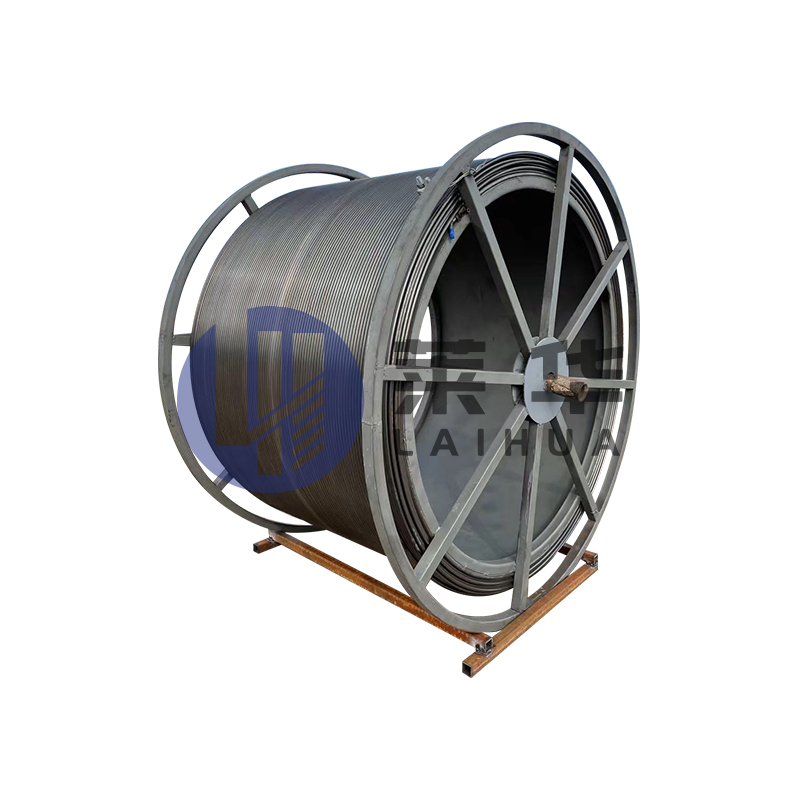
Continuous tubing, also known as flexible tubing or flexible tubing, is widely used in the fields of well workover, logging and drilling, etc. Its pro...
See Details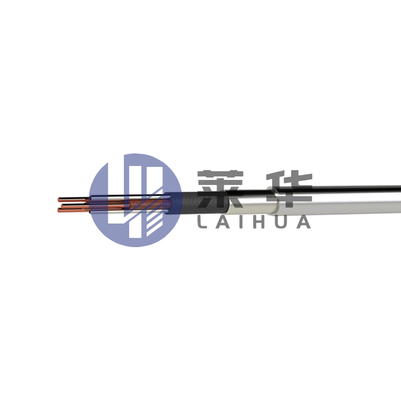
Purpose: The high-temperature testing cable, combined with the high-temperature testing vehicle, is mainly used in multi-parameter testing of heavy oi...
See Details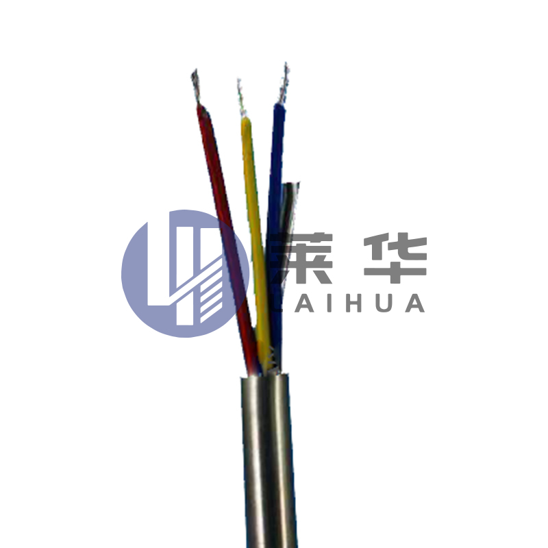
The Stainless Steel Fibre Optic Test Cable is a special test cable that combines the durability of stainless steel with the high transmission efficien...
See Details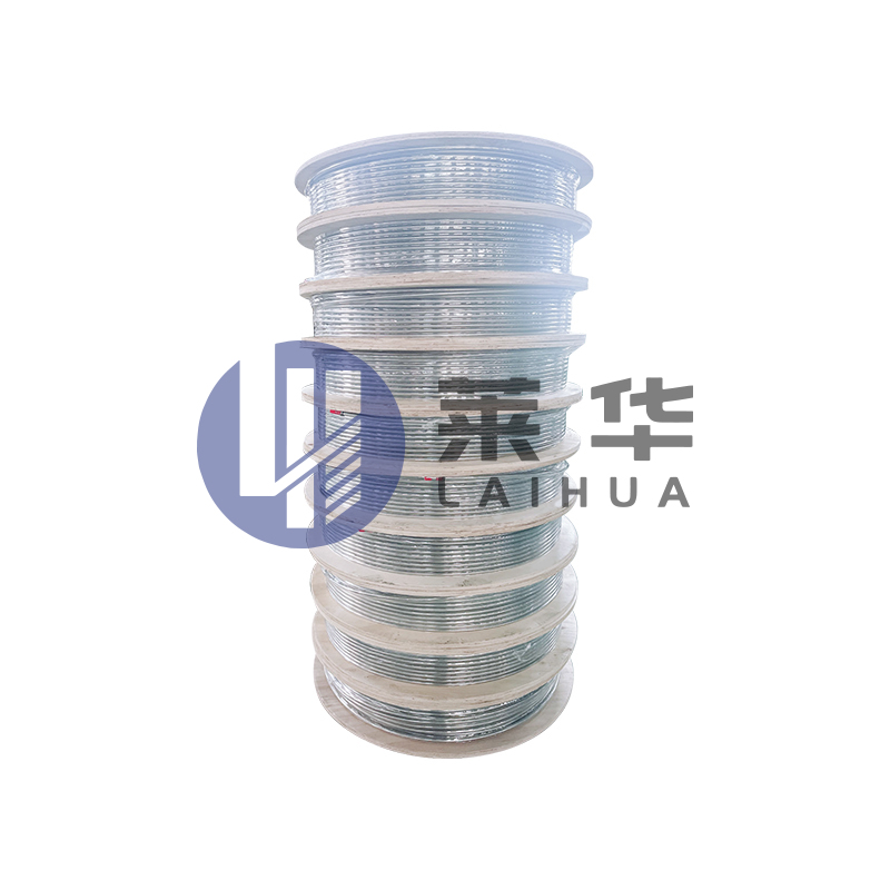
Instructions for the use of hydraulic control pipelines Hydraulic control pipeline, also known as capillary. Mainly used for underground capillary pre...
See Details
Stainless steel clad pipe is a piping system that combines the durability of stainless steel with the protection of plastic. This piping system is usu...
See Details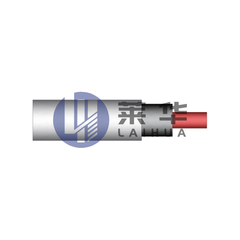
Application field:The electric induction heating system is a complete set of electric heating devices developed by our company specifically for heavy ...
See Details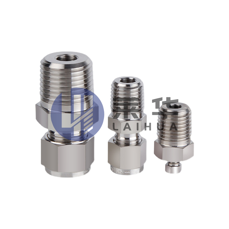
The ferrule type pipe joint consists of three parts: the joint body, ferrule, and nut. When the clamp and nut are inserted into the joint body on the ...
See Details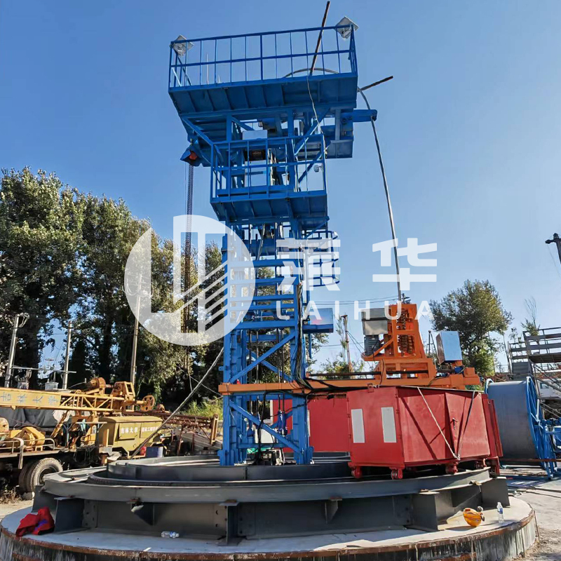
Continuous Tubing Skid Winch is a specially designed equipment for oilfield operations, which combines the design features of the Continuous Tubing Wo...
See Details
E-mail: [email protected]

Phone: +86-15996597000
+86-18252893456

Whatsapp: +86-18252874678

Address: No. 3 Xinyuan Road, Nanmo Town Industrial Park, Hai'an City, Nantong City, Jiangsu Province, China
QR code on
mobile phone



Contact Us